

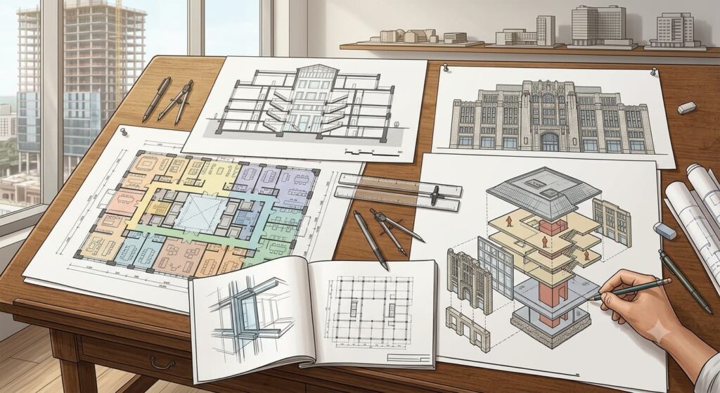
Every successful construction project starts long before the first shovel hits the ground. It starts on paper — or more accurately, in a CAD or BIM file — with a set of architectural drawings that translate a design idea into a buildable, measurable, and code-compliant plan. For contractors, estimators, engineers, and project owners, these drawings are more than technical illustrations. They are the shared language that keeps every stakeholder aligned from concept to completion.
At Digital Estimating, we work with these drawing sets every day. Whether we’re performing a full material takeoff or reviewing a complex commercial scope, the accuracy and completeness of architectural drawings directly determine how precise our estimates can be. In this guide, we break down the major types of architectural drawings used in building construction, what each one communicates, and why they matter just as much to estimators and contractors as they do to designers.
What Are Architectural Drawings?
Architectural drawings are scaled, standardized technical documents that represent a building’s design through plans, elevations, sections, and details. They follow established drafting conventions and symbols so that anyone trained to read them — an architect, a structural engineer, a plumbing contractor, or a quantity surveyor — can interpret the same information consistently.
These drawings typically cover dimensions, materials, structural systems, finishes, and the coordination between different building trades. They also function as legal and contractual documents: permitting authorities, lenders, and contractors all rely on them to confirm that a project meets code requirements and matches the agreed scope of work. For estimating teams in particular, architectural drawings are the primary source document used to measure quantities, identify materials, and build a cost picture before construction begins.
Why Architectural Drawings Matter for Construction Estimating
Before a single cost figure is calculated, an estimator has to understand exactly what is being built. That understanding comes directly from the drawing set. A well-detailed floor plan tells you square footage and room counts. A section drawing reveals wall assemblies and finish depth. A schedule tells you exactly how many doors, windows, or fixtures need to be priced.
This is why firms that offer construction estimating services treat drawing review as the foundation of the entire process. Incomplete or poorly annotated drawings lead to assumptions, and assumptions lead to budget overruns. On the other hand, a clean, coordinated drawing set allows for faster, more reliable construction takeoff services, fewer change orders, and a smoother bid process for general contractors and subcontractors alike.
With that context in mind, let’s look at the specific types of architectural drawings you’ll encounter on most building projects.
Types of Architectural Drawings in Building Construction
1. Site Plans
A site plan gives a bird’s-eye view of the project and its relationship to the surrounding property. It shows lot boundaries, building footprints, access roads, parking areas, utility connections, and existing landscape features. Site plans are essential for zoning approval, environmental review, and permitting, and they also guide contractors during initial groundbreaking and site logistics planning.
2. Floor Plans
Floor plans are horizontal, scaled layouts of each level of a building, showing the placement of rooms, walls, doors, windows, stairways, and other fixed elements. They are arguably the most referenced drawing type on any project because nearly every other discipline — electrical, plumbing, mechanical, and interior finishes — is built around the floor plan layout. For estimators, floor plans are the starting point for calculating square footage, room counts, and material quantities across nearly every trade.
3. Elevation Drawings
Elevations show the exterior face of a building from a specific viewpoint — front, rear, or side. They communicate vertical proportions, roof lines, window and door placement, exterior materials, and overall building height. Elevations are particularly useful for pricing exterior finishes, siding, roofing, and façade systems, since they show material transitions that a floor plan alone won’t capture.
4. Section Drawings
A section drawing is essentially a vertical “slice” through the building, revealing what’s happening between floors and inside walls. It shows ceiling heights, structural framing, insulation layers, foundation details, and the relationship between stacked spaces. Sections are especially important for structural and framing estimates, since they expose details that plan and elevation views can’t show.
5. Reflected Ceiling Plans (RCP)
A reflected ceiling plan shows the ceiling layout as if it were mirrored onto the floor below — hence “reflected.” It maps out light fixtures, HVAC diffusers, sprinkler heads, smoke detectors, and any ceiling-mounted equipment. RCPs are critical for coordinating mechanical, electrical, and fire protection scopes, and they help estimators quantify fixtures and ceiling systems accurately.
6. Detail Drawings
Detail drawings zoom into specific building components — a window head, a wall-to-roof connection, a stair nosing — at a much larger scale than the overall plan. They resolve ambiguity around how materials meet and connect, which is often where construction errors and cost overruns originate. Because these drawings carry so much of the technical accuracy a project depends on, many firms outsource this work to specialized CAD drafting services to ensure details are precise, code-compliant, and coordinated with the rest of the drawing set before pricing or construction begins.
7. Door and Window Schedules
Rather than a drawing in the traditional sense, a door and window schedule is a table that lists every door and window in the project along with its type, size, material, finish, and hardware requirements. Schedules are one of the most valuable documents for estimators because they eliminate guesswork — instead of counting openings manually across dozens of sheets, the schedule provides a ready-made quantity list for pricing.
8. Finish Schedules
Similar in format to door and window schedules, a finish schedule catalogs the materials and finishes used throughout the building — flooring, wall coverings, ceiling treatments, cabinetry, and paint specifications by room. Finish schedules keep material selections consistent across the project and give estimators a direct source for pricing interior finish packages without cross-referencing multiple drawings.
9. Electrical Plans
Electrical plans show the location of outlets, switches, panels, light fixtures, and wiring routes, along with circuit and voltage information. These drawings are used by electrical contractors for installation and by estimators to quantify devices, fixtures, panel capacity, and wiring runs for accurate electrical scope pricing.
10. Plumbing Plans
Plumbing plans lay out water supply lines, drainage systems, fixture locations, and equipment such as water heaters. They indicate pipe sizing, slope, and connection points. Because plumbing scopes often involve significant material and labor cost, accurate plumbing plans are essential for both installation crews and the estimating teams pricing pipe runs, fixtures, and fittings.
11. Landscape Architectural Drawings
Landscape drawings detail the design of outdoor spaces — planting layouts, hardscaping, irrigation systems, grading, and site lighting. They’re typically developed alongside site plans and are used both for permitting and for guiding on-site installation of landscape elements. For estimators, these drawings quantify plantings, paving materials, and irrigation components for site work scopes.
12. As-Built Drawings
As-built drawings are updated versions of the original construction documents that reflect what was actually built, including any field changes made during construction. They serve as the permanent record of the building for future renovations, facility maintenance, and capital planning. Accurate as-builts also make it easier to scope and price future remodel or addition projects, since the estimating team is working from the true existing conditions rather than outdated design intent.
13. Excavation Drawings
Excavation drawings focus specifically on earthwork — showing existing and proposed grading, cut-and-fill areas, and the location of underground utilities. They specify excavation depths and slope requirements to keep sitework safe and structurally sound. These drawings are essential for pricing sitework and grading scopes, since earthwork quantities can significantly affect a project’s early-phase budget.
How Accurate Drawings Support Better Estimating Outcomes
The common thread across all thirteen drawing types is coordination. A discrepancy between a floor plan and a structural section, or a missing note in a finish schedule, doesn’t just create confusion for the design team — it directly affects the accuracy of quantity takeoffs and cost projections. This is why experienced estimating providers cross-reference multiple drawing types rather than relying on a single sheet when calculating quantities.
For general contractors, developers, and subcontractors who don’t have the internal bandwidth to review drawing sets line by line, it often makes sense to outsource estimating services to a team that specializes in reading, cross-checking, and quantifying architectural drawings across every trade. This reduces the risk of missed scope, inconsistent quantities, and the change orders that come with them.
Whether you’re bidding on a small renovation or managing a multi-building commercial development, working with a provider that offers dedicated commercial construction estimating services means your bids are built on drawings that have been reviewed for coordination issues before pricing ever begins. That combination of drawing accuracy and estimating expertise is what keeps budgets realistic and projects on schedule.
Conclusion
Architectural drawings are the backbone of every construction project, translating design vision into a document set that architects, engineers, contractors, and estimators can all work from. Each drawing type — from site plans and floor plans to schedules and as-builts — serves a distinct purpose, and together they form the complete picture needed to build accurately, safely, and within budget.
For project teams looking to turn these drawings into reliable cost data, partnering with a provider that offers dependable takeoff services and comprehensive construction estimation support can make the difference between a bid built on assumptions and one built on precision. Understanding what each drawing communicates is the first step; having the right team to interpret and quantify that information is what turns good drawings into successful projects.